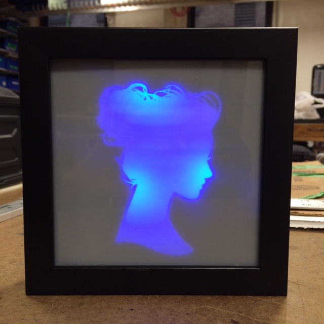
 Our assignment this week was to build a lighting controller. Since I loved the light box I made for intro to fabrication and always wanted to play with expanding it and creating different versions of it, I decided to use it as the base for this week’s assignment. Instead of just using blue LEDs, I decided to use the Adafruit’s neopixel 12 ring and add three knobs to the side of the box, one to control each color, red, green and blue.
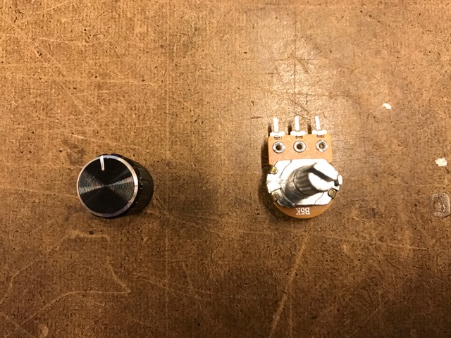
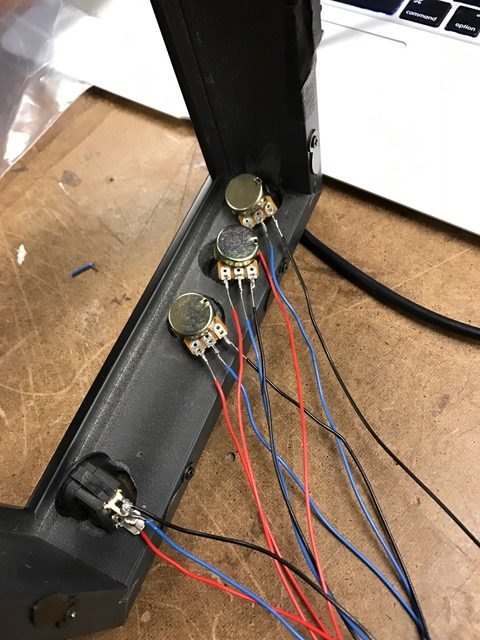
As you can see, each knob is a simple 5K potentiometer with a pretty little knob top. There would be three down the side of the frame. The schematic and the bread board set up were pretty straight forward.
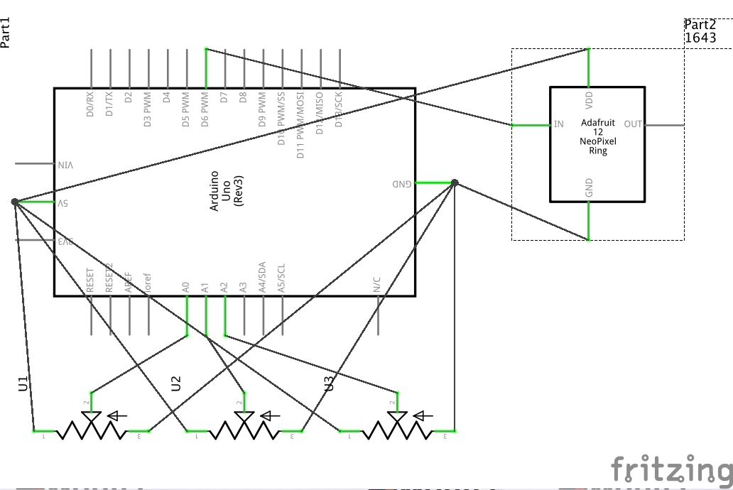

With the adafruit neopixel ring and the adafruit neopixel library, I found it pretty simple to get this up and running. I must admit, I first tried a bunch of examples from both Tom Igoe’s Github page and Adafruit’s examples. Before implementing the neopixel ring in this particular project, I wanted to get a feel for its capabilities. After a little experimentation, I found it pretty simple to write the code to set each knob to control red, green or blue.
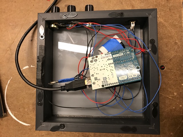
 The one addition I made from the original schematic in the example above was the switch. Instead of running all of the potentiometers directly into power, I ran the power from the arduino into the button above. So when the switch is turned the potentiometers and the light works. Here’s a close up view of the switch.
The handy little built in red light goes on when it’s turned on. I can’t claim this as a design choice because Angela kindly gifted it to me, but I did like the user feedback it gives. I did learn from Tom, I would need a button with the LED read separate — one with four outputs — to be able to code the power button as a state change. Instead for now, I built this circuit basic analog style and just overload the entire circuit with the button instead of controlling it only through code. Next I switched to the drill press and the housing. Unfortunately, I the shop had no drill bits or forstner bits that were exactly the right size so I had to use slightly smaller ones and drill through more than once per hole. Not only did this make it less attractive, but even so, the knobs did not quite fit on. Although it seemed like the wood like substance was thin enough, I realized I needed to hollow out more to make it work. Since the shop was lacking and my significant other has some great tools, I took it home.
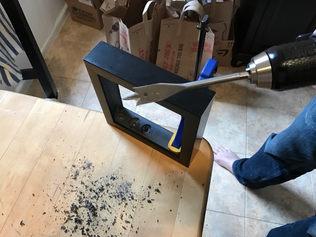
We didn’t have the right bits for his dremel either or a correct forstner bit for his right hand drill so I had to settle for the above set up. It wasn’t ideal, but it did get the prototype up and running.
I really wanted to take the final step and program an ATtiny85 with the Arduino. This is something I learned in the second half of this process will be an absolute necessity when I take the prototype to the next stage, but for now, I’m just happy to know it is possible. I also need a different light box base and different knobs. Another aspect of this project was how to solder all the power cables and ground cables together. Since the light box lets light shine through, using PCB would not be a strong choice. When I take this to the next level on another project, I would like to drill possibly little runners to run the cable along the wooden frame.
I spent so much time finding ways to space, shove and tape the innards together and still allow this to work, I should have gone back and replaced the arduino with an ATtiny85. But I never start new things like that at 8pm at night. Although I definitely do not feel this prototype is as far as I could take it, it was a really great assignment for me because I am very interested in doing further work with light boxes and it gave me a much better understanding of all of the things I would need to worry about to make this into a truly viable product.