I graduated on a Friday and on Monday I set out to build two large lighting installations for The Mill. Rama Allen, the Executive Creative Director in Emerging Tech, decided this year for AICP, he was going to do a one day art gallery exhibit showing off all of the wild and wonderful work The Mill has been building. The pieces on display ranged from AR and VR to sound sculptures and robotics. The work was incredible and the lighting installations had to maintain the quality and sensibility of the other exhibits.

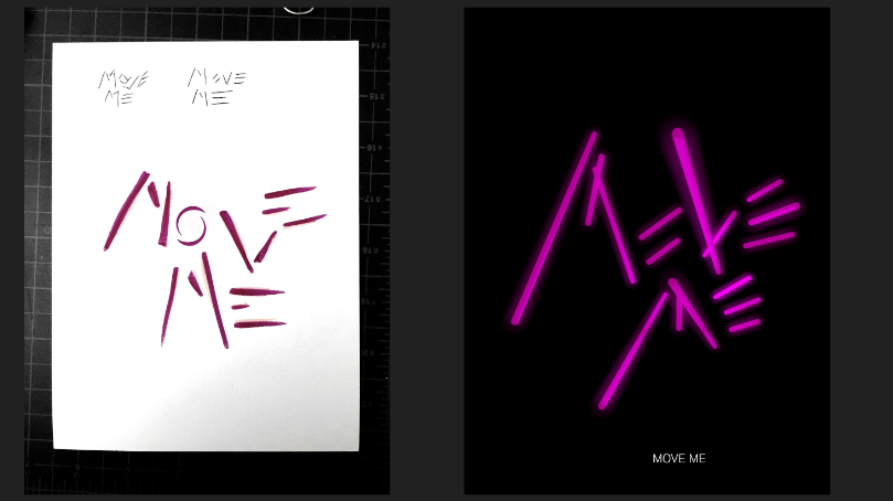
This was the gif part of the invitation to the event. The talented Kinda Akash, a creative director and designer at The Mill, created it. Kinda also did the designs for the two lighting installations that were meant to visually match the invitation. The first one is the name of the event, “Move Me.” The second is a wayfinder built out of lit tubes leading patrons through the different exhibits. The way finder was the bigger project so let’s start with that one. Here are the designs we were set to build from incorporating both the visual design layout and the actual space:
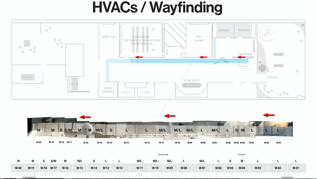
The lights were going to be hung from the HVAC (air conditioning ducts) that ran the whole length of the 6th floor of The Mill — around 100 feet. “Move Me” would be a one day installation so everything we built needed to be temporary. The HVAC was metal and the lights would be attached by magnets — they would actually be connected to the housing of the lights so it wouldn’t affect the current.

Eric Alba, the producer in charge of the project, was far more than a producer on this. Before I was hired on, he was already researching how to house Adafruit’s neopixel strips in tubes. Alba was the best producer a technologist could ask for and went above and beyond simply producing — not that producing alone isn’t a hard enough task as it is! He found plastic channels with diffuse lenses in Chinatown. To make sure this would work, we needed to test with the neopixel strips.

Adfruit’s Neopixel strips come in different forms — different numbers of LEDs per meter, different speeds for the data (the internal clock) and each of the LEDs is either RGB or RGBW. The strips are fully programmable. We went with 60 RGB LEDs per meter for most of the project. And we needed to run more than 2000 LEDs. The arduino would run out of RAM far too soon for the number of LEDs. Even the Arduino Mega was not beefy enough so before I came onto the project, the lead developer Mike Manh decided we would go with Raspberry Pi’s. A friend of his created hats for the Raspberry Pi’s — on their own, they are not capable of PWM (Pulse Width Modulation) which is required to talk to the LEDs, but with the hats attached to the Pi, it works perfectly. Since the Raspberry Pi is it’s own mini computer, it could easily control a high number of lights without running out of RAM.

Based on the design, we decided we would use four Raspberry Pi’s. There would be three lines of neopixel strips built like lego pieces that ran the length of the space and each would be headed by a Raspberry Pi — they would need power injections along the way, but each line would share a single source of data from the Pi. And then the “Move Me” sign would have its own Raspberry Pi. We decided on Raspberry Pi Zero W’s because with their tiny size, we could reuse them on many different projects. And since they are wifi enabled, they could be re-programmed from the ground without hard wiring them. I had never used the Raspberry Pi and wanted to confirm this was the best choice so I emailed Tom Igoe.
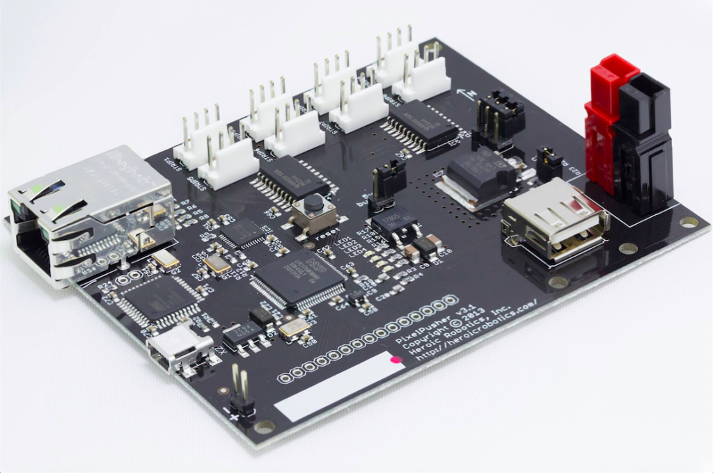
Tom suggested a Pixel Pusher like the image above. This was not in the budget for this particular project, but something I would definitely consider for future lighting installations. Tom also mentioned if we didn’t want to code in python on the Raspberry Pi’s, we could use node.js. Since the job was so big and the time was limited, I was given a developer to code the project so I could spend my time designing, building and installing the lights themselves. Fabio Piparo was fluent in python and comfortable coding the Raspberry Pi’s so we decided Mike’s plan was worth keeping for this project. And Mike had programmed a full size Raspberry Pi to test with so I started there.
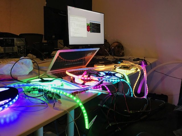
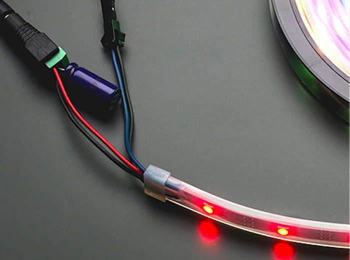
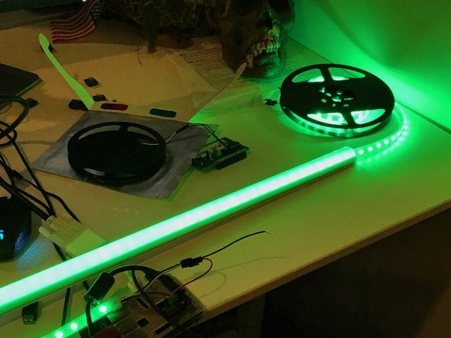
The Raspberry Pi with the PWM hat worked perfectly. I was able to light up five 4 meter rolls of 60 LED per meter pixel strips. I used one 5 volt/10 amp power supply from Adafruit for each four meter roll. This was easy to hook up by soldering a DC jack connector with a 1000uf capacitor like the Adafruit image below.
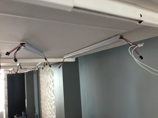
The second question was would the plastic channels and lenses Alba had acquired in Chinatown work for the look? So we tried it out:
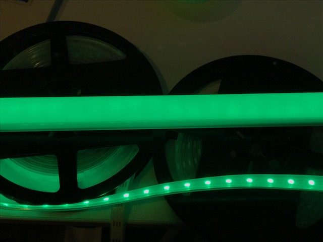
We liked the diffuse effect — we could not see the individual LEDs through the lens. This was the desired result. And then we needed to test the installation so we put the channels up with magnets to the HVAC.
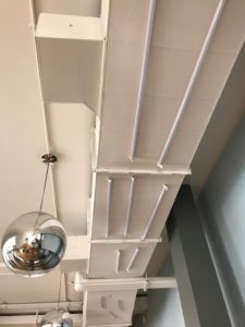
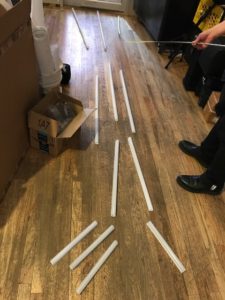
The magnets worked so we began to lay out and measure the pieces on the ground. The design called for one, two, three and four foot pieces so we needed to order and have them cut accordingly.
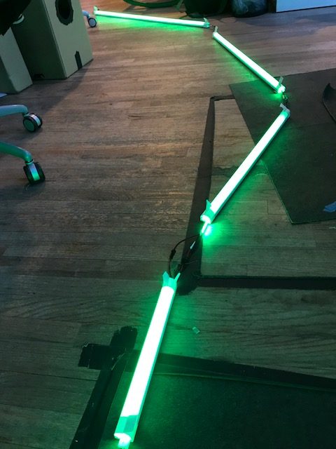
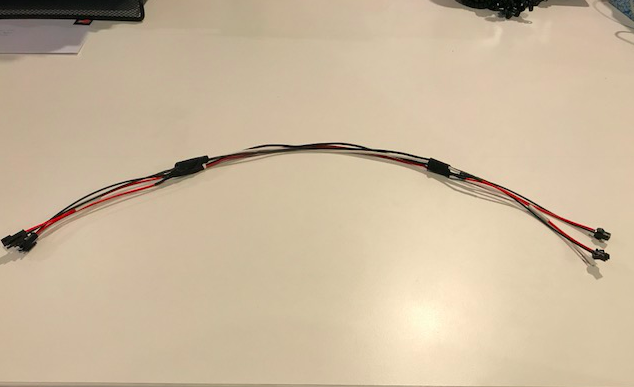
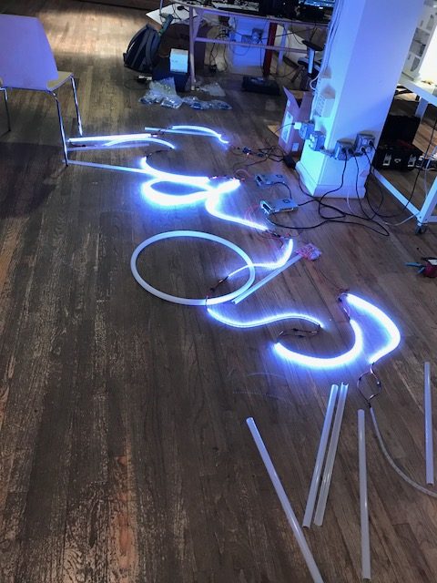
The next step was to cut a few strips in the actual lengths, solder on connectors and light them up on the ground to mirror how they would be up on the HVAC.
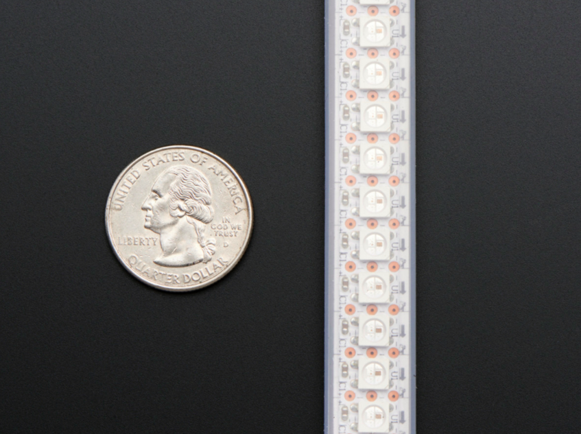
To understand better how I made these light strips, I should explain a little bit more about the neopixel LEDs. Here is an image of the strips up close from the Adafruit site.
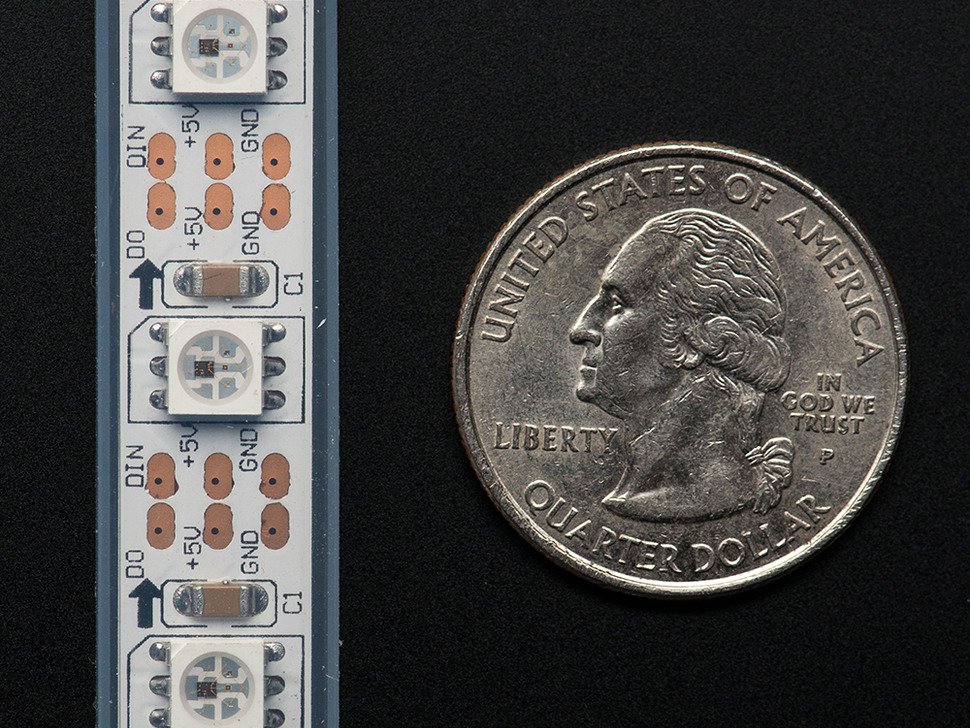
On the version we used, the copper patches are connected and there is a little picture of a scissors on top of the copper. Since the LEDs come in four meter rolls for large orders like ours, I had to cut it into the correct sized strips and solder on connectors so we could attach the strips to both power/ground and data/ground.

The strips come with a two pin JST connector at one end of the four meter strip and power and ground wires with no connectors. I decided to solder on JST connectors to the power/ground parts as well. That way we could attach each strip to other strips of different lengths and create endless linear designs — a mix and match lego light set. All of the strips that received data from a single Raspberry Pi would need to share data and ground. Some strips would be directly connected with power/ground as well, but others would need a new injection of power — a single source could not power up the entire length of the line. Data could travel far enough, but not power.

This is a photo of one of our actual strips. The copper parts are very close together. This required precise soldering. Each copper connection needed to be tinned and then wires to the JST connectors had to be soldered onto them. For the system to work, we needed two ground wires to come off of one ground copper pad. This had to be done on both sides for ever strip.
Just to give a hint of scale, I needed to make 43 one foot strips, close to 30 two foot strips and then three foot and four foot strips. The measurements were easy, 18 LEDs per foot, but the time it took to solder everything was immense. I also needed to solder JST connectors to the DC power jacks and 1000uf capacitors when we would need injections of power. Let’s just say my soldering skills were well-honed on this job!

Originally for power, we were using the 5 volt/10 amp power supplies from Adafruit as I mentioned earlier, but we were testing on a small scale. And according to the Adafruit website, it would really need a separate power source for every meter of pixel strip. Although it lit up four meters easily on the early tests, this was with a strand test that involved rainbow colors. White light pulls the most power and when I tested it with white light, the white started to turn amber the further the lights were from the power supply. I found Adafruit’s calculation to be about right — they suggest a new power source for every meter of LEDs. When we did the math based on the design it would take 2098 LEDs. That would mean we would need 65 5 volt/10 amp power supplies and a ton of DC adapters and 1000uf capacitors. This was pushing the budget too far. We needed to find another way.

One of the suggestions on the Adafruit Learn site was the above power supply. And I also found the chart below that was very helpful.

This made sense to me, but each of those power supplies creates 300 watts. This is a substantial amount of power — far beyond what I had ever worked with before. I wanted confirmation of best practices when working with the kind of power that can kill someone or burn the place down! And I’d like to add at this point that for help with the power and advice on many things from the best places to order parts to ideas for wire connectors, Alba reached out to four of the best lighting designers in NYC, Dave Crumley, Tristan Valencia, Noah Norman and Paul Carbone. Alba had worked with all of them in the past. Since it was my first sizable lighting installation, this was a huge help. They were open to my questions and gave me incredible advice. I learned so much from these guys!
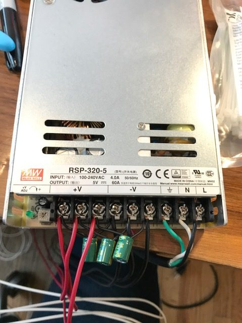
And Harry Skopas, the head engineer at The Mill, looked over my power plan. Harry also filled in more of my understanding of electrical engineering and continued to have my back throughout the process. We ordered the power supplies and wired one up above. He taught me about AC current, line, neutral and ground. We decided to keep the capacitors recommended on the site and put them between each DC power and ground output of the power supply. We ordered the fuses, but they didn’t arrive in time. We could have run out and picked them up from an auto parts store, but Harry felt it was fine to go without them. Since he’s the head engineer at The Mill, if the place burned down, it would be on him so I was okay with it.

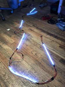
We tried out the MW power supply and it worked. The second photo shows how many feet of LEDs we decided was the most per stream of power. It looks like six, but the first foot in the second photo is powered by a 5 volt/10 amp power supply. We needed one of those power supplies for each Raspberry Pi — I didn’t want to put a large power supply on a delicate piece of equipment. I felt the 5 volt/10 amp supplies would work for each Pi. And I powered one light strip in the test directly from the power source connected to the Raspberry Pi.

To figure out the power distribution, this was my preliminary math. We figured out we needed around 5.75 Watts per foot of LEDs. Harry advised that we shouldn’t go beyond 80% capacity with any single power source. With this preliminary drawing, I separated the LEDs into power sections. Alba to be safe had already ordered 10 power supplies and with the above math, I was keeping each section far below 240 watts — 80% of each supply.
Wire gauge was another issue. The weak point of our design since it was over a hundred feet in length was the wire gauge. The JST connectors we used were only 24 gauge wire. They were not good for carrying power or data quickly over long distances. So for the in-between connectors we decided on 18 gauge wire.
Alba also had envisioned that the pieces between the lego pieces of light strips should be lego pieces of cable at a few different lengths so we could mix and match. The above image was a prototype I made for him. To keep it safe, I color coded the cables, but that would then need to be dressed when we installed it. These in-between lego pieces would also require a lot more soldering and adding in the JSTs with 24 gauge wire would create slower bottlenecks for the current. On many levels it was not the right solution.

Wire nuts was the fastest, easiest and safest solution we came up with. If we used only white wire, but built the strands one wire at a time once they were hung up so we got the right distances and used wire nuts to connect them it would make dressing the wires easier and allow us to cut out the 24 gauge JST connectors for the in-between parts. We would have to cut off the JSTs on some of the lighting strips, but this would be the easiest solution and would only happen once they were placed in their final position. (On a side note, my panel of lighting gurus gave me some other great connectors I would consider for future projects, but we were moving so quickly on this one with little time to test, the wire nuts became our solution for this one.)
I began to put up the lights and the method with the white 18 gauge wire and the wire nuts worked well. Each power supply also had three power outputs and three ground outputs. This worked perfectly with the three different data lines of wires. I used one power stream for each of the three lines of lights from each Raspberry Pi. Dave Crumley was also amazing and helped me out the last two nights installing the endless light strips. I should also add in that a few wonderful helpers soldered some parts here and there for me. And Harry lent me some of his systems engineers to help me install when they had down time.
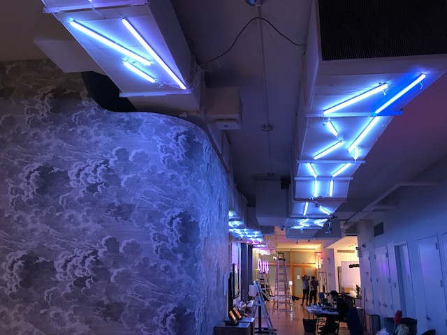
Here’s the way finder fully up and running:
And as you can see in the video, the final step after cleaning up the cables with zip ties was spray painting the JST connecters white. Now we can return to the “Move Me” sign.
The sign was meant to be scattered on the “z” access so if looked at from the side, it appears abstract, but when seen from the front, the words become clear.
These were the initial design images, but the ideal version was to match the sign to the original invitation — in other words without a second word reading “me”. The words “Move Me” would become clear with the lights flashing on and off — on the second beat the “o” and “v” would go dark revealing the word “me”. I confirmed with Kinda this would not be a problem so we dropped the second word from the build plans.
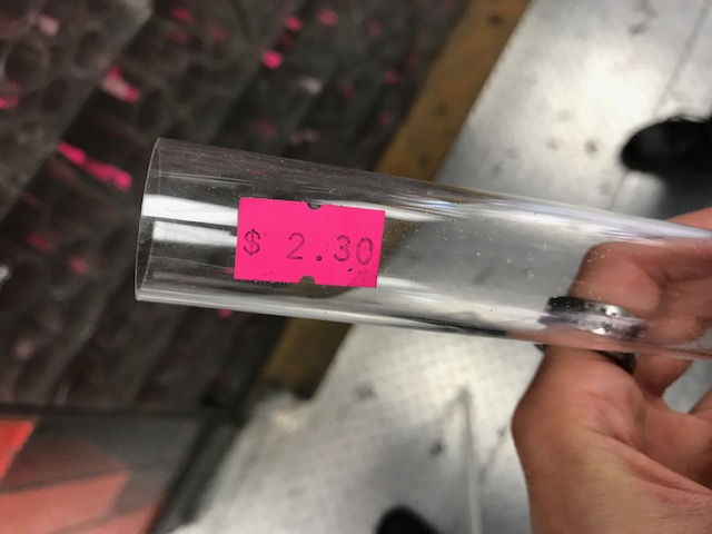
The second problem was how to build the “o”. The rest of the letters would be comprised of two foot led strips housed in clear plastic tubes lined with diffusion. We found tubes that worked at Canal Plastics.
Kinda and Alba were worried about the “O”. I mentioned a hula hoop. We could cut one open and if it was white, the exterior might serve as the diffusion. To help smooth over the points of the LEDs, we decided to test with 144 LED/meter strips instead of 60’s for the “O”. It worked — and do forgive me for not photographing the test. The second issue however was how to make the lights go all the way around. The 144 strip LEDs came in only one meter rolls, but we needed nearly two meters to fill the circle — it was decided that all of the letters would be two feet in each direction, but to size the “O” appropriately, the circumference was substantially longer.
The 144s were much harder to solder together because the copper pads were tiny and close together. We also needed a seamless attachment which meant the only thing holding together the LEDs would be the solder and clear tape to strengthen the connection — anything more sturdy and the lighting strip would not bend smoothly through the hula hoop and/or it could change the quality of the light.
After soldering confirming the hula hoop would work, I did the math and tested out the power distribution. The letters of the “Move Me” sign would need two power supplies with four points of power injection — approximately one per letter. I lay out the lights and the power supplies and tested them to make confirm it would work.
The next step was hanging them. While I spent endless hours with the way finder project, Alba spent some time researching cables and magnetized hooks. They seemed like the best way to hang the actual lights. To test, we first hung the tubes on metal shelves.
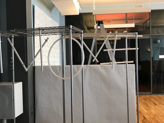
We also found little black plastic caps for the tubes to give the look of the old neon light tubes, but those would be added later when they were hung for real. While I was hanging the way finder lights, Alba got a few helping hands to get the tubes of the “Move Me” sign up. Once the tubes were hung, filled with diffusion and capped, we could add the LEDs and the wiring.

By this point, it was around three in the morning the night before the opening. Dave Crumley thankfully stayed up with me and helped me thread and wire the LEDs. We were so exhausted that we screwed up the “E” and connected a power to a ground and the reverse, shorting two of the two foot LED strips and forcing me to solder more strips before we could continue! This is what happens when you’ve been working endlessly and soldering in the middle of the night, but we got it up and running.

After we cleaned up the wires, spray painted the red and black JSTs white and lit it up, the sign turned out to be beautiful. Here’s a video the next morning just before the show opened:
SaveSave