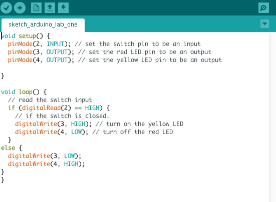
I started with the two labs for the week. The first lab involved coding a switch to change between two LEDs on the breadboard. It required the code below.
And setting up the Arduino and the breadboard as pictured in the video.
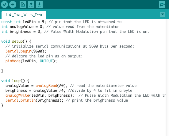
The second lab involved wiring a potentiometer to control the power to and brightness of an LED. This required the code below to program the analog reading of the potentiometer into a digital read the Arduino could understand.
Here is the potentiometer in action!
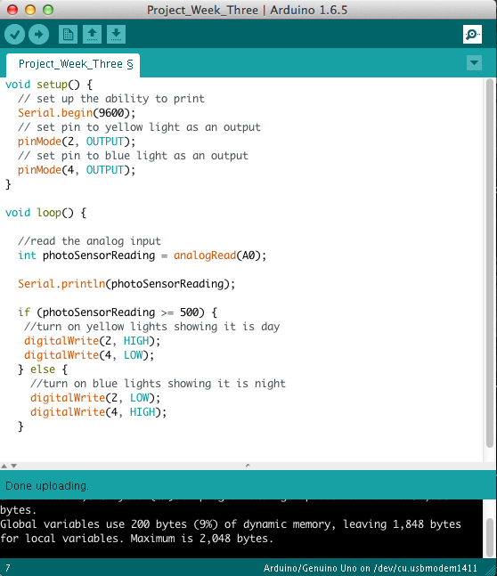
Then I moved onto my project! I decided to use a photosensor as my analog sensor. The read would tell me if the sensor is in bright light or dim light, basically day or night. To represent the time of day, I chose yellow LEDs to light up during the day and blue LEDs to light up at night. The code required information from both labs in addition to a video tutorial on reading a photo sensor. First I built the circuit and analog read to figure out if the sensor was actually working. Once I confirmed all was in order and took a look at the output numbers whether the sensor was in light or covered, I was ready to write the code below.
After finishing the code and wiring my breadboard, it didn’t work! I went back and forth through everything and could not figure it out. Finally it turned out that a single red wire had come loose. Once it was firmly pushed back in like magic the board worked. Here is a video of my little project below.
When the sensor is under the light source, the lights are yellow. Once the lights are turned off, the yellow lights turn off and the blue lights turn on representing night.