With this project, I wanted to take the light box further and try to figure out the next stage in product design interiors — how to make it as small as possible to have it self-contained, fully functional and more finished — aka Tom Igoe or children can use the buttons without fear of it breaking.
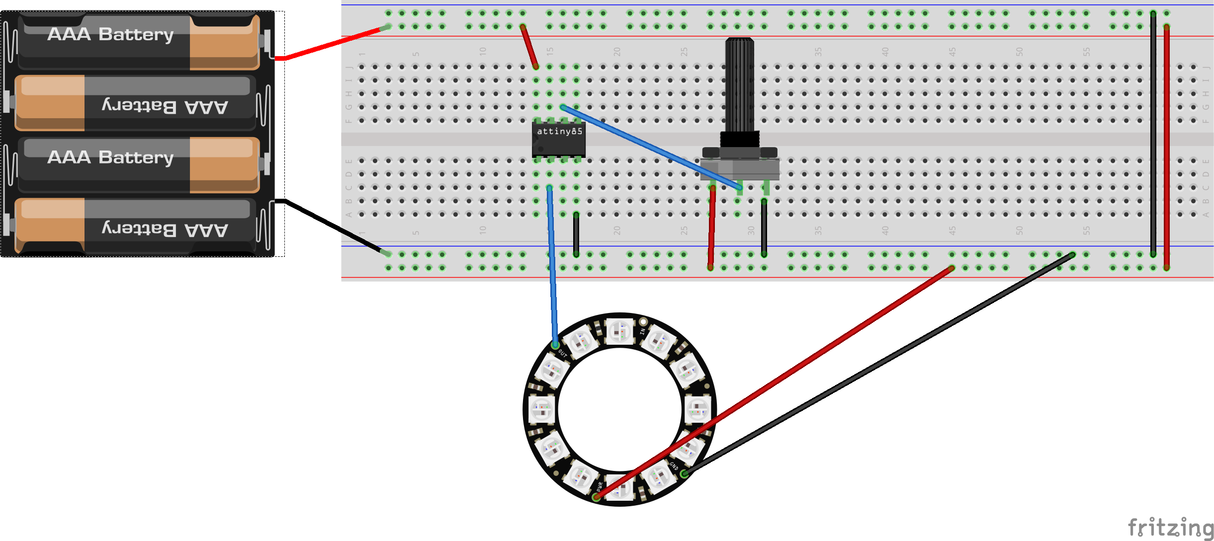
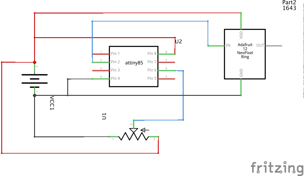
In Part Deux of the project, I used a neopixel ring and had R, G and B knobs to change the colors of the image. The truth is aesthetically I wanted only one knob and the on/off button so I thought maybe I’d switch it to HSV — hue, saturation, value/brightness — and use one knob to change the hue. This took a bit of coding time and the help of Kasper Kamperman’s blog. Without his code, I would have never gotten it to work.
Turns out, I do not like the visuals of the hue color changes. Blue was my favorite by far and with the Adafruit Neopixel library I could leave red and green with the number zero and just use the one knob to adjust the blue which essentially adjusts hue and brightness together. So I decided to not use HSV on this project, but I’m glad I figured it out for future ones.
Then I wanted to trade out the potentiometer stereo looking knob. I found this one at Adafruit, but it was only for rotary encoders. Since I wanted to play with a rotary encoders in general, I decided to buy it and try out switching the potentiometer for the rotary encoder. First I tried out the rotary encoder library with the first example. It was pretty easy.
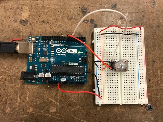
The problem came when I tried to combine the rotary encoder with the Neopixel ring code. Apparently something in the Adafruit Neopixel library is in direct conflict with something in the encoder library. Jesal was in the shop at the same time and was struggling with the Neopixel library working with the touch capacitor. We could be wrong, but I trouble shot this with cutting and pasting the code to make sure there were no typos. On one version without the Neopixel library, I was able to map the encoder’s results from 0 to 255 and when it went above or below, it reset the number to 0 or 255 respectively. It worked perfectly until I tried to add the Neopixel code. The rotary encoder could not fade the neopixel ring of light. When I turned the rotary encoder, the numbers in the serial monitor would start to drop, but then kept going back to 255 . I could feel the two pieces of code fighting for control — at least that’s the only explanation I could come up with — but anyone who knows why can correct me!
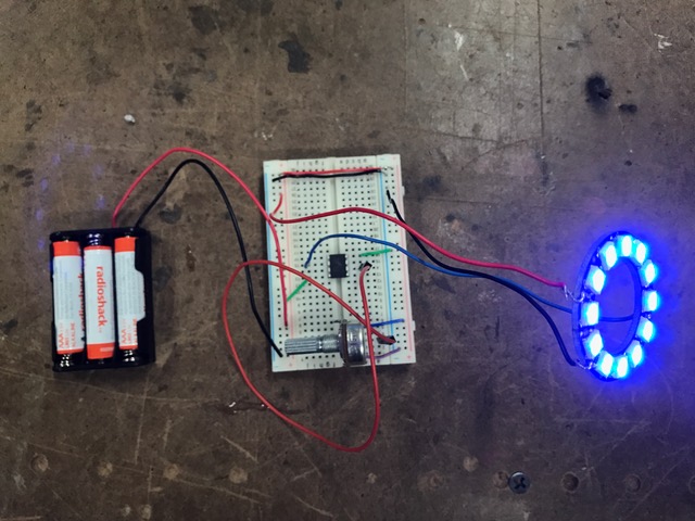
Since the main reason I was doing this version of the project was to make the final product polished and neat — aka all of the wiring neatly inside and miniaturize the circuitry — I decided to stop exploring the encoder with the Neopixel ring. I am glad I learned both the encoder and the HSV coding, but time was limited and I need to get the code onto the attiny85 so back to the potentiometer! Other than the fact that I hate the knob selections I’ve seen so far and I didn’t have time to shop further, I knew a pot would actually be ideal for the job. It would hold the former reading so if you turn off the light box and turn it back on, the light would come on at the same hue and brightness it was left at on its last use.
Here’s actually another question I had with the rotary encoder and the attiny85. I understand saving the setting of hue or brightness with the rotary encoder, BUT if I used an on/off button as an indicator and did not place it between the battery power and the attiny85, wouldn’t the attiny85 constantly be checking to see if the button state changed to turn it back on? Wouldn’t that action drain the battery? Since my iPhone and most electronics obviously have a whole save and shutdown process, I know there’s a way around this, but I do not know the answer. Tom Igoe, can you come to my rescue here?

SO with all of the above said, I looked at the different tutorials for the attiny85 and my favorite was on Instructables. First I tried out loading the blink example and it worked perfectly. And then I put my own code to control the blue of the Neopixel library with a potentiometer. Since I realize I have not put up the circuit board and code for this yet, I’ll post it here:
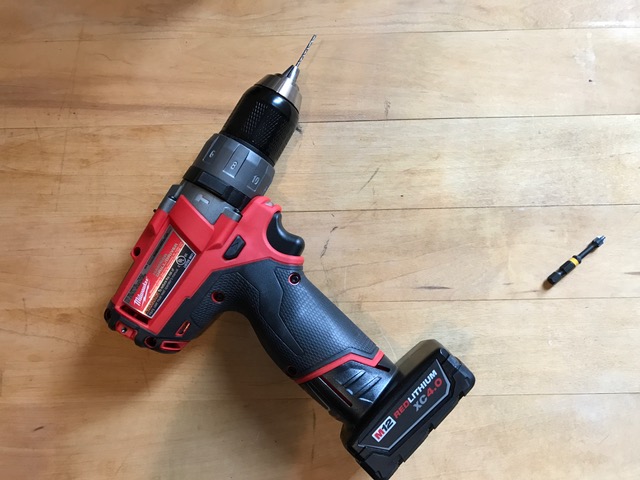
Now came the hard part — at least hard for me. How do I place all the parts and make the project kid/Tom Igoe proof? First to make the fit more perfect, I needed the drill press so with the help of my handy significant other, we pried one of the four sides of the shadowbox off, saving all of the inner metal pieces to put it back. Then I carefully measured with digital calipers to get the right sized drill bit and forstner bits to make the perfect holes. I also didn’t want to ruin the finish so I surrounded it with wood pieces — two between the frame and the clamp — and one to drill into so I didn’t shred the exit hole.
For the power switch, I used a forester bit to go all the way through, but the potentiometer was another story. The wood is too thick to just drill the hole for the tip so I needed to make a sink with a forstner bit. This took a bit of precision, but it worked!
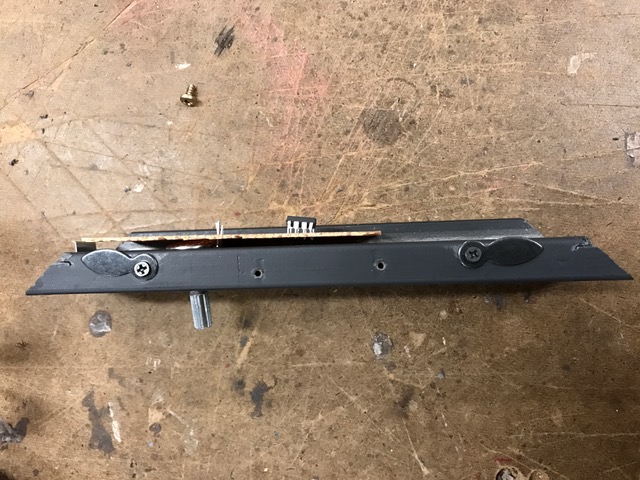
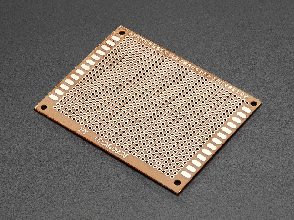
As you can see from the perfboard and potentiometer in the top left photo, I wanted the parts soldered onto perfboard and then screwed into the frame. I had trouble finding the right dimensions of perfboard, but Adafruit had this bakelite perfboard that you could easily cut with a scissors so I ordered it.
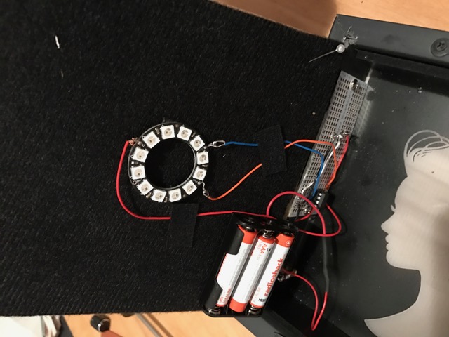
QUICK SIDE NOTE: I also bought larger perfboard that was the perfect size to place along the back. I was going to buy small single programmable neopixel lights so I could paint the picture in light just the way I liked it. Adafruit was out of stock on the lights. Then I found smaller ones I thought might work and thought I ordered them, but they didn’t come in the package. Either Adafruit or I screwed up — it was totally me this time. So I decided to stick with the ring for this iteration, but if I had used the single lights in different positions, I would have soldered them onto the full size perfboard that would be attached to the back board of the shadowbox.
So the easily cut perfboard from the first photograph was not for the back, but rather the side to hold the attiny85 and to serve as a solid back for the potentiometer. In my head it would be like my Basic Analog Circuitry class BUT I learned using mostly parts where you could bend the metal pieces to touch each other. I did NOT want to solder parts directly to the feet of the attiny85. I did find a little mount to raise the attiny85 off the board itself and house it, but even those feet were tiny. How would I solder all the ground wires and all of the power wires together on the perfboard?
The image above is from the Adafruit site, but it turns out it’s not so easy. I first tried connecting the rows in a row of solder, but the solder only really liked to stick to the copper circles, not the in-between and I had to connect it to the foot of the mount for the attiny85 which had almost no metal to work with. It didn’t work. Then I thought about stripping wire and making a metal bar across, but I didn’t like the idea of so much exposed wire. Also, if I wasn’t careful with the solder, it could easily connect to the next row and that would kill the whole circuit.
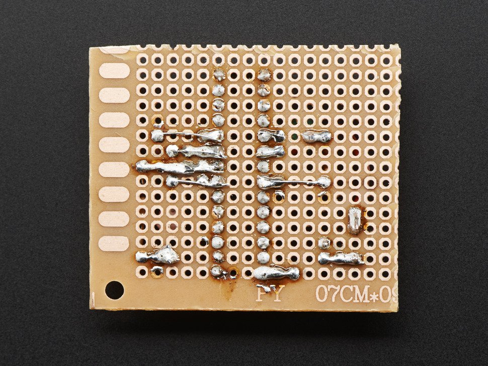
SO I also happened to have the adafruit perfboard modeled to duplicate the breadboard with holes already connected with copper. However, it was too large for the space so I had to use my wire cutter to cut the pcb to be the right size. This piece was NOT meant to be cut so it took a bit of elbow grease and tools that weren’t really meant for the job at hand, but I got it to work!
My soldering also had an additional hiccup. I checked each piece as I soldered it, but there were a few points that had to be done at once before I could test. That’s when I learned the potentiometer had stopped working. I traded out the original wires I had soldered to the Neopixel ring on the last version of the project and replaced them with softer, stranded wire I liberated from the junk shelf. But despite how careful I was, the ring turned on, but would not change based on the potentiometer movements. I checked every single connection with the meter and found the weak wire was the one to the pot resistance shift. That made sense, but when I traded it out, it still didn’t work.
I thought the weak point could be the input wire for the ring so I cut it, changed out the wire and re-soldered. That changed nothing. So I started wiggling wires with the power on. It turned out that although the new wire to the resistance leg of the pot worked, it was still not connecting perfectly. It read, but not consistently well. I added a bit of solder and noticed that when it was pressed firmly against the side of the frame, it worked well. Not the ideal solution, but since I had to screw in the perfboard, it would work.
SO I drilled holes with the help of my significant other — one held the perf board in place and one held the drill since thanks to the button and potentiometer, it was not flat and hard to clamp. Once the perfboard was bolted in, the connection worked perfectly!
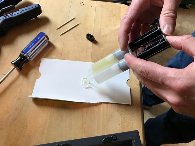
Then we used epoxy, mixed it together with a toothpick and smoothed it with the tiny broken pieces back into the corners of the frame. Then we put the two metal staples back in place and nailed them back in. We used the drill as a weight since we didn’t have frame clamps.
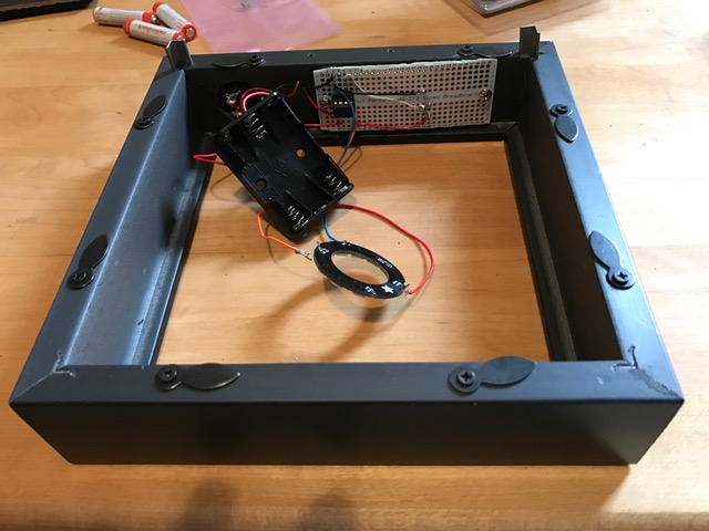
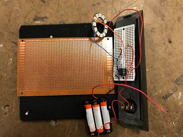
then the final step was attaching the Neopixel ring in place. My first thought was to solder it to the perf board, but the connections were working well and I did not want to mess with that. My second thought was to loop through the perfboard with fishing wire, but it turned out that a third option was even better. Velcro. Since the Neopixel ring was so light and the back that came with the shadow box loved to stick to Velcro, it was the perfect match. I also was originally going to screw the battery pack into the back, but the Velcro worked so nicely with the ring, I tried it with the battery pack as well and it worked brilliantly!
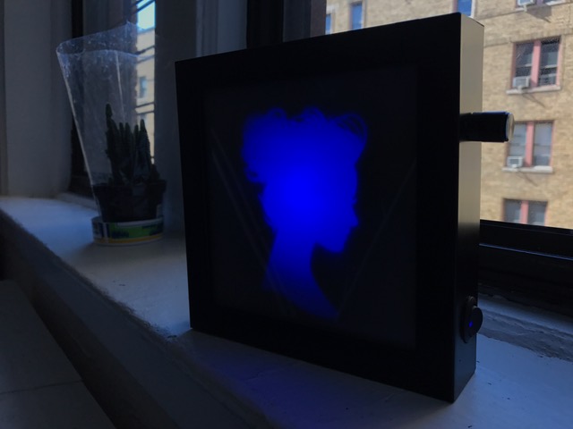
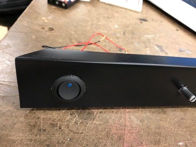
The box was finished! The knob controlled the brightness/hue and the power button worked perfectly. Although there is more I’d like to do in the future with light boxes, I felt I proved to myself that I could make it look more or less like a finished product. And the next step for me is making my own pcb. Product design I realize is something I really enjoy and would love to learn the steps to do it in a way that could be mass produced.