This project was one of the most enjoyable experiments I worked on this semester. I mean, how could it not be? I have wanted to build a robot since birth and there’s definitely something intriguing about photovoltaics. Put together the two things and we have the makings of a super fun project!
Joakim Quach — my partner in crime on this project — rebuilt Jeff’s original circuit with me duplicating what we had in class. Just a quick explanation of this circuit — Photovoltaic cells generate power, but not enough to carry much of a load without a bit of help from the circuit.
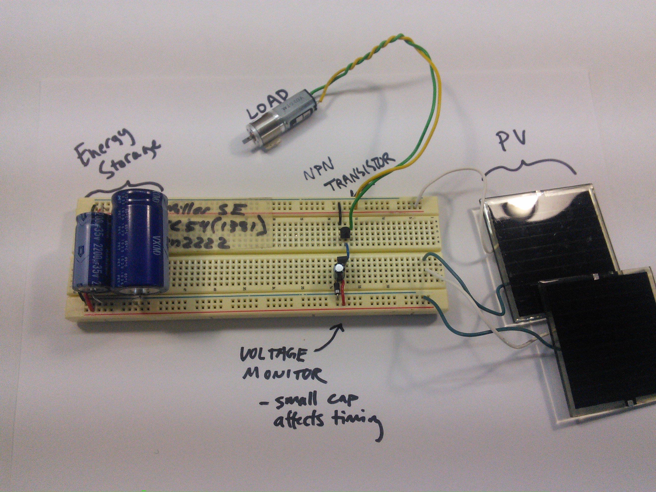
The set up below uses a transistor to keep power from going into the load at first. The PV cells are able to create more power that is stored in the larger capacitors that you see to the left in the photo below from Jeff’s website. The little black part that looks nearly identical to the small black transistor is the voltage detector. In this circuit, the motor is always connected to power, but it does not connect to ground until the voltage detector reads 3 volts — this way it is not actually a part of the circuit…yet. Then at 3 volts the detector triggers the transistor to open up the switch, completing the circuit. And the tiny capacitor you see on the circuit is used to store up a bit more energy to keep the voltage detector and hence the transistor open for a little bit longer than it would be open without it. This circuit allows the photovoltaic cells to build up high enough voltage to run the motor. Otherwise the amount collected would never be enough to manage the load. Make sense?
Our capacitors, load and I believe voltage detector were slightly different than the original set up. We had a slightly different motor — we actually tested two — our voltage detector was 3 volts and I believe Jeff’s was actually 4.2 AND we had slightly different sized storage capacitors.
The motor is a substantial load so we started our experiment by replacing the motor with an LED, a much smaller load, to make sure the circuit worked. It lit up beautifully. Then we moved onto motors. We got a twinge in class, but no real action so Joakim and I set out to take the circuit apart and put it back together piece by piece — testing each part of the circuit on its own — to see how we could improve on it.
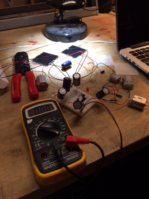
We had many questions that needed to be answered. The first one was whether or not we needed to order a new motor. We knew the original circuit was not giving enough power to really run any of our motors. A twinge is hardly enough to create any real movement for a robot! But why wasn’t it? First we tried experimenting heavily with capacitors. As you can see from the photo above, we started adding many more large ones. The more we added, the longer the LED stayed lit up — and the longer it took to charge them up — but it did nothing for the motor. Were we not getting a high enough voltage for the motor? We needed to test it.
So we pulled out a steady power source and tested the motor directly outside of the circuit. First off, this proved the motors actually worked — just not in the circuit. And it turned out that the motors could turn at 3 volts — and we had a 3 volt detector — BUT only when attached directly to the power source. Why? We measured the amperage in the circuit and it was substantially lower than when attached directly to the power source. We wondered about a way to boost the amperage. Later we learned in class that we could have added a potentiometer, but at the time it hadn’t occurred to us.
We tried playing with the size of the capacitor next to the voltage detector. The size made absolutely no difference when it came to starting the motor, but we realized it could really mess with the circuit. If the capacitor was too large, it held enough charge to keep the trigger detector switching the transistor on, but not enough power for the motor or even the LED at times to start. We figured out why by touching an LED to the capacitor directly and watching it light up. Once we used the LED to drain the extra voltage, the circuit would once again work with the LED, but still not with the motor. After playing with different capacitors, we decided the perfect size was the 10uf/50 volt capacitor. Smaller did not hold it open for long enough and larger was running into the problems I wrote about above, BUT still the motor was not turning on.
Over the course of our tests we realized with lower amperage, the motor needed a bit of a higher voltage to start up, but then it could run at a lower voltage. We tested the photovoltaic cells. They only could do about 4 volts each, but with the two in series and a lot of capacitors we could definitely get it up higher, the problem was the voltage detector. No matter how many capacitors were added to the circuit and even with the photovoltaic cells in series, if the switch would open at 3 volts, we would never get the power high enough for the motor to start — we learned quickly a motor needs a higher voltage to begin even if can remain spinning at a lower voltage. We researched larger voltage detectors, but none were being sold close by and if we ordered them online, they would never get here on time! I emailed Jeff and he had a bunch of 4.2 volt detectors. He left them in his mailbox for us.
The 4.2 voltage detector did the trick! BUT with the motor we favored, it sometimes needed a bit of help. If the motor was ready to turn — it wasn’t caught between two turns — it would start on its own. Or if we turned it once with our hands with no power, it easily turned when the power came on. Over time in the circuit, we reached a point where it started on its own every time, but we also got our hands on a tinier motor from an old CD player — also thanks to Jeff!
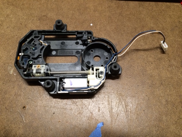

When we started thinking about what the robot would do, we decided his head would spin so the smaller motor would be a better option both for the circuit and for the needed action.
With the smaller motor it worked every time! We also honed our circuit based both on functionality and aesthetics for the robot. Our final version required these parts:
2 Photovoltaic cells — in series
3 4700uf/10 volt capacitors — to store more energy in the circuit (total storage capacitance = 14,100uf)
1 10uf/ 50 volt capacitors — to keep the voltage detector open longer (total timing capacitance = 10f)
1 4.2 voltage detector — triggers the transistor (actually flipped on at 4.8 volts)
1 2222A transistor — acts as the switch to complete the circuit once the voltage is high enough
1IN40 diode — to ensure the energy flows in only one direction
And here’s the schematic:

After taking all of the measurements, we learned that upon triggering, the potential energy in joules = 1/2CV^2 = 1/2(4700uf x 3)(4.8)^2 = 0.03384 joules (Note: the 4.8 is the voltage amount we found triggered by testing the voltage detector when it triggered. The 4700uf is the size of each capacitor. Since we have three in parallel and the capacitance when they’re in parallel is equal to the sum of each one, hence times three.)
Now that everything worked, it was time to solar the parts and build the final robot.

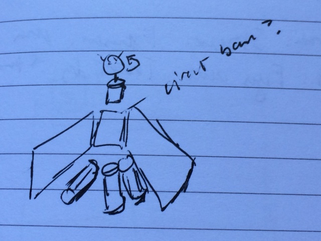
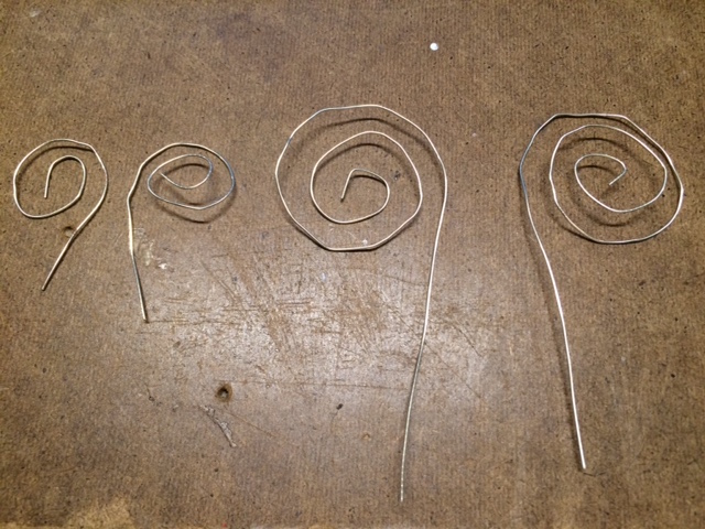
The solar panel would be the winds. The robot would stand on the capacitors. The main circuitry would be his body and the motor would function as his neck, but we needed a head! I found the perfect styrofoam ball in the junk bin, but a white ball is hardly enough to give him a personality so I began stripping wires and playing with designs for antenna.
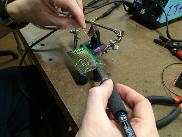
And I also found two small black buttons for eyes. After soldering and testing the circuit to make sure it worked on the piece of PCB instead of the breadboard, we put the finishing touches on bringing him to life!
And here’s our final solar robot. He’s sort of a Tim Burton style robot butterfly. I’m still unsure of his name, but he’s very cute in my biased opinion.
