Kinetic Energy Project NYU ITP from Jamie Ruddy on Vimeo.
The Experiment: To build a kinetic project that created the most energy in the form of light.
PEDAL TO POWER
My first thought for this project was immediately a stationary bike with a motor hooked up to it. The more you peddle, the more energy is created. When I was a kid my parents had a stationary bike in their bedroom. I spent hours watching movies and biking. I saw it as a way to solve two problems at once. Work out and help generate energy.
However, since none of us had a stationary bike, we would need to first purchase one. The most cost effective option would require a lot of fabrication to attach the motor. The time and cost would be too high for this level project Maybe for a final. So we went back to the drawing board.
PULLEY POWER
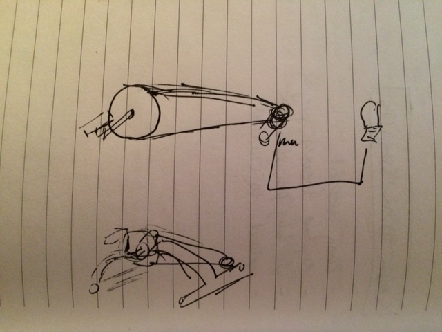
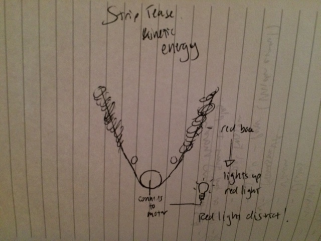
Our professor, Jeff, had shown us a pulley system in class. This seemed much lighter on fabrication. Marcelo immediately thought we could use it with a punching action. As much as I loved this idea, I boxed a bit for exercise in my day and the movements unfortunately did not quite line up. All three of us were trying out the movements the pulley system would need and soon it came to me. Strip tease! What if the pulley was a boa and the more you carried on with your burlesque act, the more power you generate? And the light could be red aka red light district!

Angela loved the idea and immediately started singing Roxanne by The Police. She was on fire with the tag line puns. Poor Marcelo was not as happy with this concept. I fear it was a bit emasculating. The challenge was creating the most light — not the most amusing way to do it — so energy potential would make the final decision. Angela and I took a trip to Home Depot to find out.

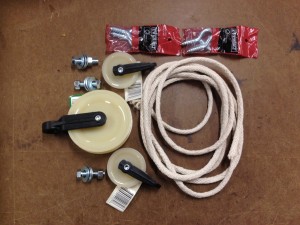
With the help of a lovely employee, we left with enough parts to see just how much power we could generate.
We built a circuit similar to what we did in class. We used rectifiers to change the motors AC power to DC power and tried many different experiments with different sized capacitors — this also led to much discussion and googling over putting them in parallel versers in series. Parallel was the correct choice for us.
We got the light to turn on, but no matter what we did, it wasn’t generating much power. We tried with adding a switch to allow the capacitors to “charge” before powering the LED. It helped, but the power was not enough. The three of us together tried different positions to see what would give the most movement and in turn the most power.

Notice I look anything but attractive in my attempts! I resemble the Hunchback of Notre Dame more than Gypsy Rose. And our power options were not improving vastly. I could tell mechanically this what not ideal, but my fabrication skills are still on the weaker side and cost was an issue. We decided to consult with Ben Light to see if there was a simple thing we were not seeing.

Ben — the fabrication genius that he is — was rather horrified by our thrown together pulley system. His suggestions all involved buying parts we didn’t have the time or the money for, but he also inspired another attempt at the pulley system – the tug of war. He was right mechanically because with the rope and the smooth, plastic pulleys we had bought, this would make the rope sit the soundest, but we felt it would not help generate any greater amount of power.
I kept coming back to the way the gears work on a bicycle. The larger gear was required to make the smaller gear move faster, but how do we build this? We didn’t have time to order gears.
In addition to keeping costs down, it’s also great building things out of recycled parts so the three of us made a trip to the junk shelf at ITP. We found quite a few interesting throw aways. First there was a magic bullet blender which we cracked open to check the motor inside. We realized the motor would require magnets dropped in to generate power so it was a no go, but it reinforced for me how to build a motor from scratch — not that I have ever done that…at least not yet. There were also no good working gears inside to reappropriate, but Marcelo found another motor. I still have no idea what it came from.
Although we never figured out how useful it would be as a motor, a quick spin and we soon realized it would make a great gear mount! The thick fan like blades were easy to grip and spin. We would need a large gear on it that would turn a smaller gear mounted to the motor. But what would we use for the gears?
The acrylic top from an old record player saved the day. Marcelo jumped into illustrator and designed gears we could laser cut out of it. There was a struggle both to get the laser cutter to make it through the thickness of the acrylic — I think six passes finally worked – and working with illustrator to get the teeth of the two gears to match. Eventually we got the two gears cut in a way to fit perfectly. If you look closely, you can see the original cut attempt before we realized that scaling a vector graphic also scales the teeth! But aesthetically it actually turned out a bit interesting.
Meanwhile, I was googling around to figure out if there was a way to get more power out of the circuit and I found out about a boost converter — I watched the great tutorial video Jeff posted and passed it along to another group in the class. Seemed like a great solution. The pulley had gotten us up to 5 volts at moments and I knew the gears could at least pull that, but how much in the end? The contest was to produce the most light. And lighting a tiny LED in a breadboard wasn’t going to cut it. Another quick search and I found at Tinkersphere we could pick up a boost converter to get us from 5V to 12 V. That would be a substantial gain. But we also needed to find a bulb that would fit 12 Volts.
Angela and I left Marcelo to finish printing the gears while we went to the light store and Tinkersphere. Angela immediately spotted a blinding 12V light. We knew it would give us the best chance. Then on to Tinkersphere for the Boost Converter and Crazy Glue.
Marcelo was ready with the gears when we got back and we put it together. The glue took a bit to set, but once we got it to hold, we knew we were onto our final build. The circuit lit up well at first and Angela reminded us that we had taken the switch out of the circuit. We put the switch in and the boost converter and the bulb lit up brilliantly!
We also found the metal mount on the junk shelf which worked perfectly for the bulb. All we had to do was solder the wires to make them a little longer and we had a fabulous light stand.
We later found out that we had not hooked the boost converter up correctly so it was not doing it’s job. The one we found was different from the one in the tutorial and when the 12V lit up well, we assumed it was working. It turned out our new mechanical system was so much more effective than the last one, we could light up a 12V bulb without a boost. I still feel silly about the boost converter, but at least we learned a lot about mechanics in the process!

Here’s the final circuit that was actually pulling the weight (trade the small LED for the 12V lightbulb):

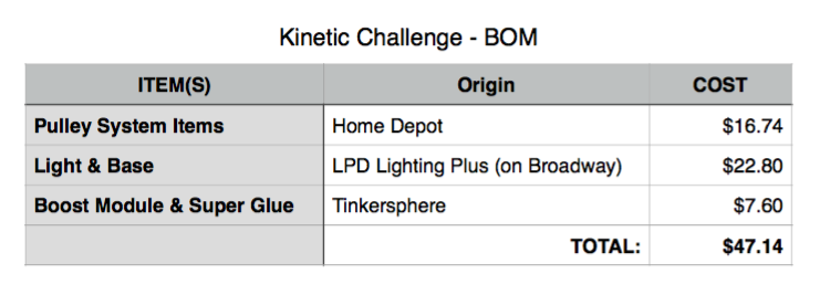
The project BOM was not too bad when all was said and done.